This page contains an overview of the Autoleads PC9-406 stereo adapter. This adapter allows for the plug-n-play installation of an aftermarket head unit in 91 Toyota MR2s with the premium sound option. The premium sound system uses a 14 pin harness that does not fit any of the Metra adapters. Using the PC9-406 harness allows you to install an aftermarket head unit while retaining the stock amplifier and without having to cut any wires. If you're not planning on keeping the stock amps, you can still use the PC9-406 to get your power and ground leads and such, but it's probably overkill.
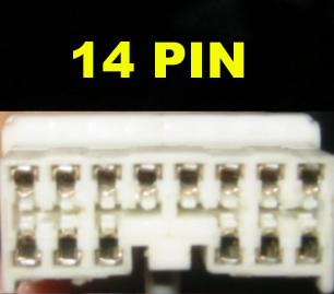
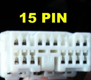
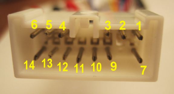
For reference, here's pics of both the 14 pin and 15 pin stock body side audio harness. The PC9-406 only works with the 14 pin connector.
This page just covers the adapter. Information about the MR2 premium system in general, as well as other approaches that don't rely on using the PC9-406, can be found here. I strongly suggest reading this discussion thread as well for some important background info.
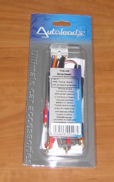
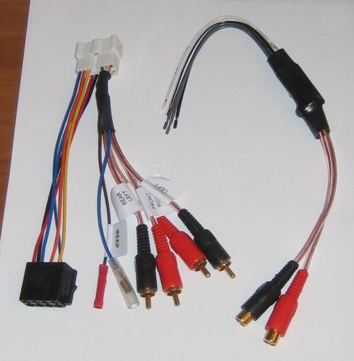
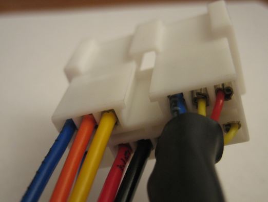
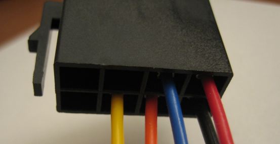
The packaging and harness are shown below.
The following table lists the connections provided by the PC9-406. In short, it's in agreement with the mapping described in this thread .
| Pin # | BGB label | PC9-406 Connection |
|---|---|---|
| 1 | AMP | blue-white wire with male bullet connector |
| 2 | ILL+ | orange wire in ISO B |
| 3 | +B | yellow wire in ISO A |
| 4 | MUTE | blue-black wire with female bullet connector |
| 5 | FL+ | Front left RCA plug center |
| 6 | FR+ | Front Right RCA plug center |
| 7 | ANT | blue wire in ISO D |
| 8 | ILL- | no lead present |
| 9 | ACC | red wire in ISO E |
| 10 | GND | black wire in ISO C |
| 11 | GND | Connected to ALL FOUR RCA signal grounds |
| 12 | BEEP | brown wire with "beep" label, butt splice crimp connector |
| 13 | RL+ | Rear Left RCA plug center |
| 14 | RR+ | Rear Right RCA plug center |
Note that as shown in the photo below, the pins are numbered right to left so as to be consistent with the BGB convention for male connectors.
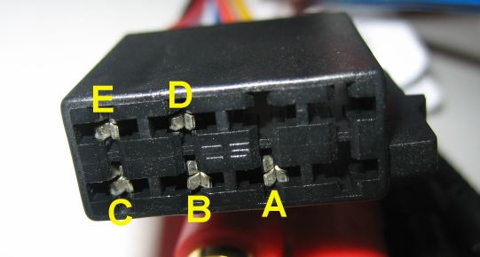
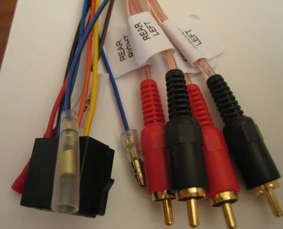
Lastly, for completeness, here's some pics of the wire side of the connectors and the RCA & bullet leads.
 Up to the top