MKII Toyota MR2 Audio Installation How-To Guide
This page gives the details of a DIY aftermarket stereo installation in a MKII Toyota MR2. The installation is performed in a 1991 MR2 with the stock "Premium" system, but a lot of the information here is applicable to all MKIIs. This is not an all-encompassing guide; my intent is to simply provide one possible approach and provide some details that may be of use to anyone contemplating a similar install. Since every audio installation is unique, however, you will likely run into issues not covered here.
What this guide is: An account of the MKII MR2-specific aspects of the stereo installation. Removing the stock door panels, adapting the stock wiring harness, fitting an amplifier rack, running wires through the firewall... all the nuts-n-bolts aspects of an aftermarket stereo installation that are unique to a particular car.
What this guide ISN'T: Lots of things won't be covered here, such as the basics of system design and tuning, sub box fabrication, wiring basics, etc.... all these things are covered in great detail elsewhere on the web.
This was a long term project for me, so I have lots of pictures and comments. I've done my best to keep things organized, with varying degrees of success. This page contains:
Disclaimers:
- The information here was current when I wrote it. Part numbers and part availability can change. If you notice something seriously wrong on this page, let me know and I'll try to keep it updated.
- Use this guide at your own risk. Not responsible for skinned knuckles, electrical fires, or profanity overheard by impressionable family members.
- This guide is a work in progress. Comments, corrections, typos, and alternate approaches
are welcome and should be sent to "smspam @ comcast.net" with "MR2 audio" in the subject line.
The basics
Stock Premium System
The 91 Toyota MR2 was available with a premium audio system composed of a double-DIN head unit, two amplifiers, two tweeters, two woofers, two rear fill speakers, and a subwoofer. The tweeters are mounted in the sail panels, the woofers in the front bottom of the doors. The rear fill speakers are behind the seats on the sides and the subwoofer is mounted in the driver's side storage compartment behind the seat. The amplifiers are mounted behind the driver's seat as well, behind the plastic panel the holds the engine lid release lever. The stock system produces fairly decent sound as stock systems go. The stock head units, however, often have trouble reading CDs as they get older. Replacement stock head units are extremely expensive, so I made the decision to go with an aftermarket head unit. Integration into the stock wiring harness is non-trivial due to the odd connector used for the head unit and the issues with bypassing the stock amplifiers. It's possible, but I decided instead to do a complete re-wire of the system.
Upgrade paths
Head unit
I'd strongly recommend going with an aftermarket head unit, unless you're absolutely set on having a stock look. The stock stereo is expensive to fix/replace and lacks a lot of modern features. The dash can accommodate a double-DIN unit or two single-DIN units, so you have a lot of freedom here. Basically just buy whatever head unit you want based on features, cost, appearance, personal brand bias, whatever. The two things I would recommend looking for are high-voltage pre-outs (4V or more) and MP3 compatibility. The high voltage pre-outs work towards reducing the impact of noise, which can be a problem for some installs. I've found MP3 capability to be incredibly useful, so much that I almost never listen to the radio any more. If you rip and encode from your own albums with a good encoder (such as Lame 3.93) you really don't give up much in sound quality, especially in a car environment. You can also fit tons of audiobooks on a single CD.
Tweeters/Woofers
The stock locations aren't the best, but they aren't terrible, either. I kept the stock locations to keep the stock look. Others have made custom kick panel enclosures to house both the woofers and tweeters. It improves imaging, but encroaches on footwell space, which may or may not annoy you in the long run. I'd recommend getting a good set of component speakers and mounting them in the stock locations. The stock woofer location can handle most 5.25" speakers and some, but not all 6.5". You may have to make a spacer ring out of MDF for some speakers. You'll have to check yourself, or try posting on the audio section on the MR2 Forums to see if someone else has installed your speakers before. I'd also recommend mounting the crossovers next to the amp, rather than in the doors, but this is personal preference.
Rear speakers
I'd leave these out. The stock locations are very close to the seats, and speakers mounted behind you can cause problems in terms of imaging and overall sound quality they're not set up carefully. Furthermore, the interior of the MKII MR2 is small enough and causes enough reflections that I don't think you need separate rear fill speakers. I'd put the extra money into better front components or a better amp instead.
Subwoofer
A single 10" or two 8" subs is more than enough for a SQ install in a MKII. If you're more into SPL, go wild, but you're on your own. Bear in mind that the MKII MR2 cockpit is very small, and the subwoofers will most likely be mounted directly behind your seat. You simply don't need as much cone area for the same perceived loudness as you would with subs mounted in the trunk of a sedan. I went with a single 10" behind the passenger seat, rather than two 8"s. I like having one of the flat shelves behind the seats available for storage; for a small cooler for long trips, for the T-tops, or just to throw random crap back there without having to worry about messing up a speaker cone. I'd recommend a sealed enclosure, since space is at a premium. You can get truck boxes that fit pretty well and are reasonably cheap, or you can get a box custom made or make it yourself. Just measure the shelf, figure out the volume you need for your chosen speaker, then dust off the trigonometry and geometry you learned in high school.
Amplifier
If you omit the rear speakers as suggested above, you can get buy with a two-channel amp for the components and a separate sub amplifier. Or you can get a 4 channel amp, as I did, and bridge two channels to drive the sub. I ended up with 150 watts per channel for the component speakers and 300 for the sub. This is plenty, IMHO, and I think you can get buy with less. If you decide to include rear speakers, you can just run them off the head unit. I mounted my amp in the front trunk, which gives short cable runs to the speakers, head unit, and battery. It's also a less obvious location for thieves to look. The downside is the potential for noise from the various electronics mounted up there, particularly the power steering.
General wiring
I recommend rewiring the whole system, and not trying to re-use any of the stock components or wiring.
The stock wiring is a bit on the small side and also tends to corrode in areas like door harness. IMHO trying to re-use portions of it is not worth the trouble. Take your time when running the new wires and cables, and try to mark everything. A set of multicolor electrical tape is handy when you're trying to hook up four identical sets of speaker wire to the cross over. You can always pay to have someone do the install for you, but I typically don't trust the car stereo places to do it right, especially on a non-trivial install such as ours. Plus, by doing it yourself you'll learn a lot and be better prepared to trouble shoot should problems arise in the future.
My System
My install consisted of:
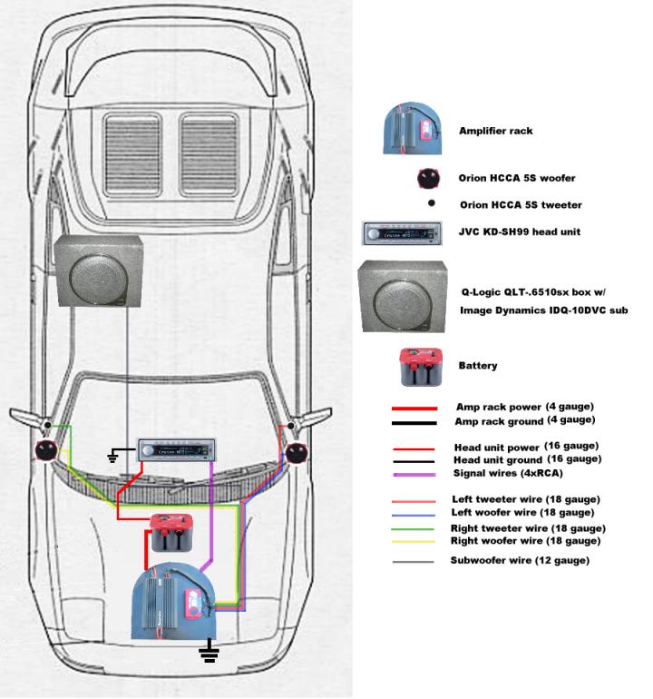
- A Phoenix Gold XS4600 4-channel amplifier mounted in the front trunk
- Orion HCCA 5S component speakers in the stock locations (5.25" woofer in the door, 1.5" tweeter in the sail panel)
- A single Image Dynamics IDQ-10 subwoofer in a Q-logic QLT-.6510SX truck box behind the passenger seat
- A JVC KD-SH99 Head unit.
More detailed information about the components is contained in the install sections below. Pretty much every component in my install has been discontinued and/or replaced with a newer model with a different name, so the above list is pretty much worthless as a buying guide. Hopefully it will at least serve to give you some ideas. Before I get into the details, here's some general info about this guide you should know:
- I use MDF, or medium density fiberboard, for just about everything. You end up making a lot of curving cuts and drilling lots of holes, and with MDF you don't need to worry about going against the grain or hitting a knot. It also finishes smoothly. The downside is that it's pretty heavy, and makes a lot of dust when you're working with it. Plywood would probably work just as well in some areas, such as the amp rack.
- I try to be consistent in my terminology, but I use the following words interchangeably: Tweeter cover/sail panel; RCAs/signal wires/interconnects; mids/woofers/speakers; sub/subwoofer; and head unit/HU/deck. Hopefully everything will be clear from context.
- A lot of the pics are on the crappy side, because at the time of my audio install, my digicam was a bit on the crappy side. I've since upgraded, so if anything is unclear in the pics let me know and I'll try to get a better picture. This is assuming the part in question is readily accessible and easily photographed; I'm probably not going to be willing take my door apart and unmount the speakers to get a better pic.
- You can install the components in any order, but I recommend installing the amp first, since that's what everything else connects too. It's also good to have it already installed so you can use it to check the woofers & tweeters when you get to that step.
Installing an amplifier in the front trunk
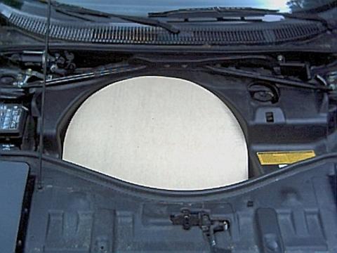
This section covers the installation of a 4-channel amplifier in the front trunk (or frunk) on a simple MDF rack. The rack fits on top of the spare tire and held in place by the plastic frunk trim piece and the tubular spare tire framework. There's no actual bolts or screws connecting it to any metal, it's just held in place by its own weight and by virtue of being a tight fit. I've had no issues with it moving around during autocross or track days.
Building the amplifier rack
I used a scrap piece of solid core foam insulation to make my template. This is basically a big piece of pink styrofoam, roughly 3/4" thick, that can be bought in 2' X 8' sections at any hardware store for a few bucks. It comes in very handy when prototyping. It can be cut easily with any serrated knife. I started with a 2' X 4' piece of this stuff and started trimming it down, test-fitting it in the frunk repeatedly as I went. Once I felt it was close to the shape I wanted, I traced the outline onto the MDF and made my first pass. Here's a pic of one of the test-fittings:
This was sort of an iterative, trial and error build. The best advice I can give is to start big and trim it down from there, thus ensuring a tight fit. Here's a rough sketch of the rack dimensions:
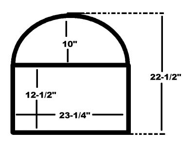
The bottom section is a rectangle 23-1/4" wide by 12-1/2" high. The top part is sort of a slightly-blunted half circle, with a radius of 11-5/8" at the base decreasing to 10" at the top. Total height of the rack is 22-1/2". Again, start large and trim it down, test fitting frequently. This seems as good a spot as any to mention that the amp rack, woofer spacer rings, and tweeter mounts can all be made from a single 2' x 4' piece of MDF if you're not too wasteful.
I ended up having to make a few notches in the perimeter of the rack to run the various cables. I also took out two notches along the bottom to clear a coolant hose and the spare tire frame. Once I was done cutting, I painted it black and screwed down the amplifier and crossover.
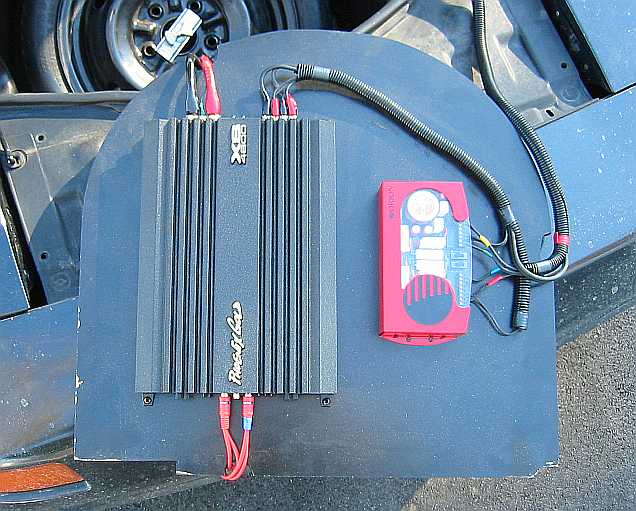
Note the notch at the top for the power wires, the notch on the right side for the speaker wires, and the center notch at the bottom for the RCAs. This pic was taken a couple years after I finished the install, and the bottom left corner of the rack is starting to show wear. I don't really see the need to repaint it.
Here's one more detail that will be of interest to...pretty much nobody. The crossover frequency of my amp is adjusted by replacing DIP resistors which are accessed from the underside of the amplifier. Since I didn't want to have to unmount the amp to get to these, I drilled out two large holes in the amp rack for access:
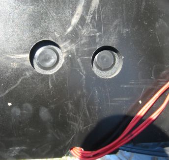
Of course, once I finished my install and started tuning it, I found that I was perfectly happy with the stock crossover settings and never used my clever access holes. I only mention this in case your amp has some component that can only be accessed from underneath (which, incidentally, strikes me as a bad design). If this is the case, you may want to make some provision for access once the amp is mounted on the rack.
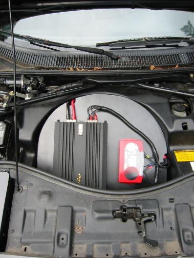
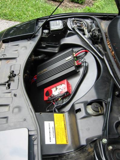
Here's some pictures of the finished product as mounted. The wiring is covered in the next section.
Wiring the amplifier
This section covers wiring the amplifier. It's broken down into
Power, ground, and turn-on leads, signal wires, and speaker and subwoofer wires. Some general wiring advice:
- Make good connections, crimp hard, and when in doubt, solder. The wiring will be subject to a good amount of vibration, and you don't want anything coming loose.
- Use gold plated connectors when possible. They're really not that expensive and resist the elements better.
- Once you've figured out what you need, buy supplies from one of the big discount online audio supply stores, such as Partsexpress.com. The retail mark-up on connectors, wires, and other basic supplies is obscene, especially at places like Best Buy or Circuit City. You can buy wire by the foot off a spool pretty cheaply at Lowes or Home Depot.
- Avoid drilling new holes when possible. Use a grommet any time you run wires through a firewall.
- Secure wire runs in several places with zip ties.
- Leave yourself some slack, perhaps as much as a foot, on each end of a wire run. You might need to make changes later, and you don't want the wires pulling tightly on the speaker/amp terminals anyway.
- Leave enough slack in all wires at the amp rack end so that you can remove the rack without having to disconnect anything, in case you need to get to your spare. Or, get a bunch of quick disconnects.
This section will be short on words and long on pictures. All you're really doing is pulling back assorted paneling and carpeting to route the wire. It gets a little complicated, so to help keep things straight I made this conceptual diagram of the wiring layout:
Power, ground, and turn-on leads
The only tricky part with the power leads was getting a good crimp on the large 4-gauge ring terminals. I didn't feel like paying for a specialty tool I was only going to use once, so I improvised. First, I secured the lead and terminal in a bench vise.
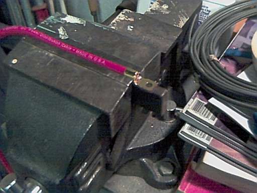
Then I whacked the top of the terminal collar with a mallet and cold chisel. This caused the top to curl in slightly. I then repositioned the terminal in the vise and crushed it, which collapsed the collar into the wire. I filled the open end of the terminal with as much solder as I could get in there. All told this made for a very solid connection.
For the power lead, I spliced in an inline fuse holder about a foot from the terminal.
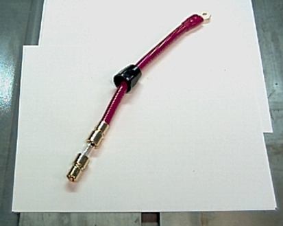
The HU constant power wiring is similar to the amp power lead: ring terminal crimped on to the hot end, then a fuse holder within 12" of battery. In fact, both the HU and amp lead can be tapped from the same bolt on the stock + battery terminal, as shown below. I used 16 gauge wire for the HU constant power.
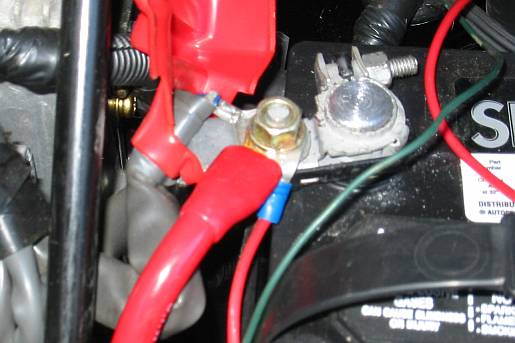
Here's a larger pic showing the power wiring for the head unit and amp. Note the fuses, 60 amp for the amplifier and 15 for the HU. I pulled out the wires so they'd be more visible in the pictures; they look a lot neater when they're tucked back behind the battery. They look neater still when they're completely hidden by the plastic spare tire fairing.
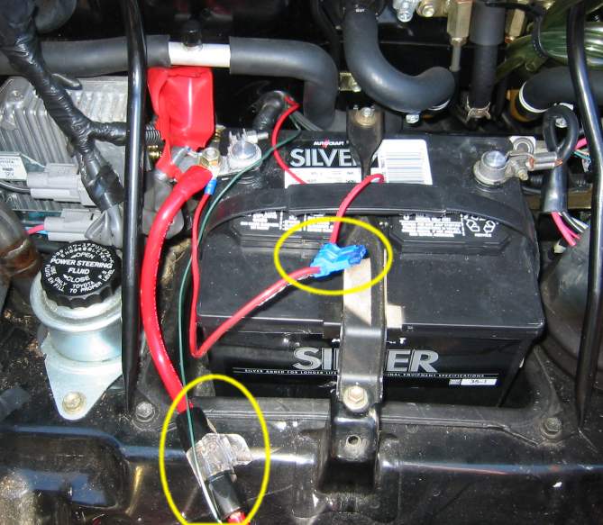
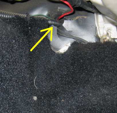
From here, the amp wire runs to the amp (surprise), and the HU constant power wire runs to the HU through a grommet immediately behind the battery. The thin green wire visible in the above pic is the amp turn-on lead. It runs through the same grommet as the HU constant power lead. Here's a close up of the grommet behind the battery:
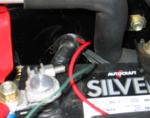
Note that the speaker wires for the passenger side woofer and tweeter run through this grommet as well. Here's a view of the grommet from the other side. It enters the cabin in the upper left corner of the passenger's footwell, just above the edge of the carpet:
The amp is grounded to a heavy bolt in the front of the frunk, one that also secures the metal tubing framework for the spare tire cage. I sanded down the metal beneath the bolt and used a lock washer to ensure a good connection. The manual for my amplifier specifically said not to ground to the negative battery terminal.
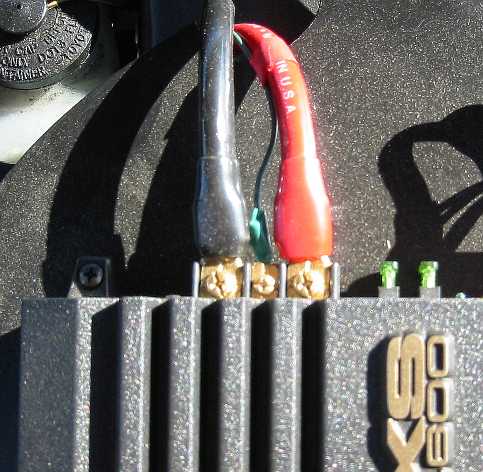
The amp power, ground, and turn-on leads are all connected to the amp with crimp on ring terminals, as shown below. I used a fairly thin wire for the turn-on lead, 20 gauge or so, since it doesn't have to carry any significant amount of current. I also secured the turn-on lead to the power lead with electrical tape at several points along the run.
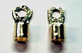
I actually had to grind down the sides of the ring terminals for the amp side connections. I used a bench grinder then cleaned them up a bit with a file. Before is on the left, after on the right:
Signal wires
For signal wires, I used inexpensive twisted pair RCAs with gold connectors. Don't buy anything with "monster" in the name. I ran two pair, one L-R pair for the components, and another pair for the subwoofer. I could have used a single RCA for the sub, since I only have one, but I thought it made sense to go ahead and run a pair in case I decided to upgrade later.
The RCAs run from the bottom of the amp through the notch in the bottom of the amp rack. I marked the subwoofer RCAs with a band of blue electrical tape on both ends so I could distinguish it from the component speaker RCAs.
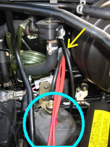
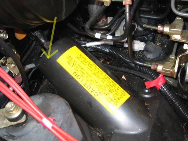
I ran the RCAs through the firewall using the speedo cable grommet shown below. It's to the immediate left of the brake booster. Note the large cylindrical part with the rubber dust cover located between the battery and steering column . You can't miss it, but I circled it in blue anyway. This is the power steering pump. Try to route your signal wires as far away from this as possible, as it's a common source of noise. In this picture my RCAs are laying right across it, as a result of moving things around to get these pics. Before putting everything back together I moved the RCAs further over to the right.
In general, the Frunk is a veritable mine field of potential noise sources. The power steering pump is the most noxious offender, though. You may have to try routing you cables a few different ways to get a noise-free install. In hindsight, it might have been easier to use a different grommet for the RCAs, perhaps one over on the passenger side. Once you find a routing that works, secure your RCAs with some zip ties to keep them from shifting around.
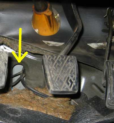
Here's a view of the grommet from the driver's side footwell. The grommet enters the cabin above the carpet near the top of the accelerator pedal.
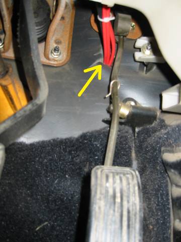
From here the RCAs simply run up behind the center console to the HU, secured in a few places along the way with zip ties.
Speaker wires
For the component speaker runs I used 18 gauge wires, bought by the foot off the spool at a local audio store. I ran two pair to each door so that I could keep the crossovers in the frunk with the amp. I prefer this approach to mounting the crossovers in the door, but plenty of people have mounted their crossovers in the door without issues. I used 12 gauge wire for the sub, bought off the spool at Home Despot.
The amp side connections are made with gold plated crimp on ring terminals.
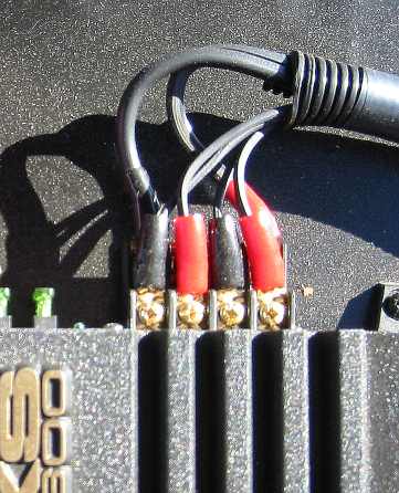
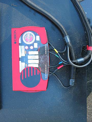
The speaker wires run immediately to the crossover which is mounted next to the amplifier on the amp rack. The color codes for the wires coming out of the crossover are:
- Red : Left Tweeter
- Blue : Left Woofer
- Green : Right Tweeter
- Yellow : Right Woofer
I used flexible plastic split loom tubing to keep the wiring neat. It can be had for around 20 cents a foot from various places online. I ran the sub and speaker wires together in the same loom. The wires run through the notch on the right side of the amp rack and down the floor of the frunk to the firewall just behind the steering column.
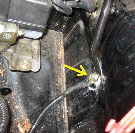
Behind the steering column is a small hole which leads into the driver's side footwell. I wasn't able to get a good picture of it, but its rough location is shown below. It's easier to get to if you remove the plastic steering column guard, the one with the big yellow sticker. I ran the subwoofer wire and driver's side speaker wires through this hole. The passenger side speaker wires split off from the loom at this point and run behind the battery up to the grommet used for the HU power, as shown in the previous section.
There's a large keyhole shaped opening in the driver's side footwell, roughly between the clutch and brake pedal. It's behind the carpet so you'll have to pull it back some to see it. Note that the firewall is two layers at this point, so after you push the wires through from the frunk side, you'll have to fish around in the keyhole to pull them into the cabin.
The subwoofer wire then runs behind the dash and down the center console to the sub behind the passenger seat, as shown in the sub wiring section.
The left and right woofer and tweeter wires run along the outside edges of their respective footwells to the kickpanel, where they join the door wiring harness as shown in the picture below. This pic is of the passenger's side wiring, the driver's side is a mirror image.
From the kick panels, the wires run along inside the accordion door harness. The process of running the wires in the door harness is described here.
This is a good time to test the amplifier. I didn't have my head unit installed yet, so I used a portable CD player with a mini-to-rca plug as a source. I jumped the Power lead to the turn-on lead with some alligator clips to get the amp to turn on. If you don't have your speakers hooked up yet, you can connect them temporarily and run them in free air to test, or use a pair of home theater or computer speakers. Just make sure whatever you use has enough impedance and can handle the power output of your amp. There's no point in doing any fine tuning at this stage, but it's good to at least make sure everything is working.
Removing the stock door panel
This section covers removing the door panel, a necessary step to installing the tweeters and woofers.
This section will be short, since I already described the whole process here, and it's also covered here. Just one thing I should add: on my door wiring how-to page, I suggest leaving the window up, as it gives you more room to root around inside the door. For a speaker install, however, I recommend leaving the window down, since this is the only way to ensure you've left enough clearance between your woofers and the window glass. The catch is that it's easier to run the speaker wires with the window up. So, you can pick your poison, or do it twice. I actually ran the speaker wires while fixing the door wiring, then mounted the woofer another weekend.
Installing aftermarket tweeters in the stock location
The stock location is not the best for imaging, but it's not that bad either. I specifically chose a component set with a low tweeter crossover frequency to help "blend" the sound together. The ORION HCCA 5S manual recommends a tweeter-to-woofer separation of no more than 24". The stock locations on a MKII MR2 are 16" center-to-center.
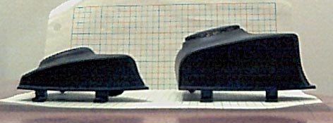
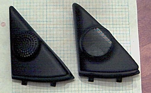
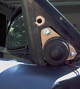
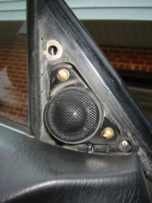
91-92 vs. 93+ Tweeter covers
One cheap and easy upgrade for 91-92 owners is the 93+ tweeter covers. These are much larger than the stock 91-92 covers and have a grill instead of drilled holes. They are available from the dealer and are a direct swap for the old style covers. Some side-by-side pics of the covers appear below, the 91-92 covers are on the left and the 93+ covers are on the right. The 93+ covers allow you to mount a larger tweeter, and may give you more freedom in aiming the tweeter more towards your ears. I've also heard people say that the finer mesh grill in the 93+ covers transmits sound better than the drilled holes in the 91-92 covers, but I can't vouch for this myself.
The part numbers, official names, and list prices for the tweeter covers are:
67491-17041 Door - Outside mirrors - Inner cover (Right) $14.55
67492-17041 Door - Outside mirrors - Inner cover (Left) $14.55
Custom tweeter mounts from MDF
Let me preface this section by saying I went to way too much trouble making these mounts. I didn't mind, since I enjoy wood working and had all the necessary tools, but there are much easier ways of mounting the tweeters. For instance, some people have used plumbers tape or even just double-sided tape with good results.
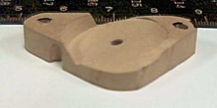
The mounts were made from 1/2" MDF. After I'd removed the stock tweeters, I cut a small triangle out of cardboard to get a rough estimate of the shape of the space. I used this as a template to cut the MDF. I then used a belt sander to shape the MDF more accurately to fit in the recesses. I used the stock tweeter bracket to transfer the mounting holes to the MDF pieces and then drilled new holes. Also, several partially drilled holes were needed on the back to clear the heads of the mirror mounting screws, to allow the MDF pieces to mount flush. To find where clearance holes were needed, I drew on the heads of the protruding screws with a black marker. I then pressed the MDF piece into place, and then drilled wherever marker had transferred onto the back of the MDF. This was basically trial and error, so I'm afraid I don't have any exact measurements. I also cut a small notch in the back to run the tweeter wire.
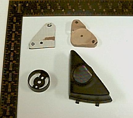
Here's a picture of the unfinished tweeter mount, the cardboard template, the tweeter mounting cup, and the 93+ tweeter cover for reference.
On the front, the trickiest part was the angled circular recess for the tweeter cup. I clamped the MDF pieces to a jig made from scrap wood that inclined the pieces ~ 20 degrees. I then used a 1-7/8" Forstner bit in a drill press to make the recess. I drilled a small hole through the center of the recess into the notch in the back to run the wire.
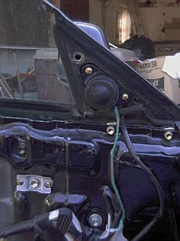
I did a quick test fit....
...then I finished it with black spray paint. I took the original brass mounting screws to Home Despot and bought matching screws 1/2" longer, and some washers. Here's the final product, as mounted.
Of course, once the tweeter cover is back in place all the hard work is invisible, which is why I think the simpler approach of double sided tape or plumbers tape makes more sense.
I unplugged the stock tweeter plug, tucked it out of the way, and ran new wires along the stock wiring path. I soldered the tweeter leads to the speaker wire, but in hindsight it probably would have been good to buy another set of disconnect terminals. There's sort of a channel in the door panel that you can run the wire along, I've hi-lighted it light blue in the pic below. The thicker wire to the right of the tweeter wire is for the power mirror. There's a few more pictures of the wiring setup in the woofer section.
Installing aftermarket woofers in the stock location
As mentioned above, pretty much any 5.25" and a lot of 6.5" woofers will fit in the door. The only thing you have to watch out for is drivers with really deep baskets, since you may rub up against the window glass when it's rolled down. This brings up an important point:
- Be sure to roll the window down before beginning the install
You want to be certain you have enough clearance, and this is the only way to be sure. Rolling the window up or down while you have the door panel off is non-trivial, so think about this before you begin. If you want to be certain of whether or not a given speaker will fit in the stock hole, check the MR2 Forums or Crutchfield. For deeper drivers, you may have to make a spacer ring. This is pretty straightforward, and is covered in the next section.
Creating a spacer ring
This section describes making a spacer ring out of MDF for mounting woofers in the stock location. Using a spacer ring buys you a little extra room for deep drivers, and also allows you to use drivers with a screw layout different from the stock speakers without having to drill into the door metal. I made my rings from 1/2" MDF.
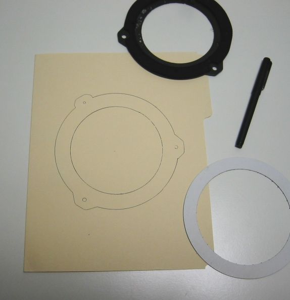
The first step is to remove the stock mounting ring. Use it as a template and trace the outer edge onto a sheet of MDF. You can also use the stock ring to mark the location of the holes for the 3 screws that will hold the spacer ring to the door. Next, trace the inner circle of the spacer, based on the required mounting hole diameter for your chosen woofer. My component speaker set came with templates for tracing out speaker holes, basically a cardboard doughnut looking thing. If you don't have one of these, you can just use a compass and the specs for your particular woofer. Try to center the hole on the spacer as best you can. The stock ring, cardboard doughnut template, and resulting spacer outline is shown below as drawn on a manilla folder. I did this after the fact for the sake of this web page. Obviously, you want to save yourself a step and just trace directly onto the MDF.
Note that the outer profile of the ring doesn't have to match the stock ring exactly. I made mine slightly larger in the area of the three screw hole tabs for a little extra strength. Once I was happy with the design, I made two quick cuts with a table saw to free the spacer from the larger piece of stock I had started with. This made it easier to maneuver it when making the screw holes and the finish cuts. I drilled the screw holes with a drill press and finished up the outer edge with a band saw.
The last step is to cut out the inner speaker hole. First drill a small starter hole inside where the speaker hole will be. Then use a jig saw or coping saw to roughly cut out the hole. To finish up the inside, I used a drum sander mounted in a drill press. This allowed me to get the speaker hole nice and round. Just go slow and work your way outward until you hit the line. You could also use a hand file or Dremel for this step.
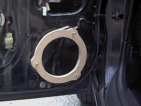
Here's a pic of test-fitting the spacer ring:
I spray painted it black and called it done. I took the original mounting screws to Home Despot and got matching screws 1/2" longer, plus some washers.
Installing the woofer
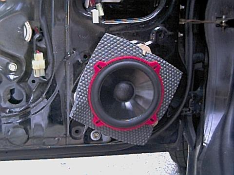
Making the spacer ring was the most time-consuming step of the woofer installation. The rest is fairly straightforward. I stapled one of those foam speaker baffles into the spacer ring to protect the speaker from moisture in the door, then did another test fit with the woofer to make sure it cleared the window glass.
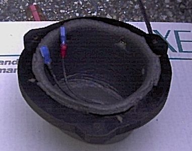
Then I trimmed back the foam baffle around the mounting ring of the speaker. I cut a hole in the bottom rear of the baffle to run the wires, and connected them to the speaker with spade terminals. I used crimp-on terminals, and wrapped the base of the terminals with a small band of color-coded electrical tape (red for positive, black for negative.) I "pre-crimped" the open end of the spade terminals lightly with a set of needle nose pliers. This gives them a tighter fit on the speaker tabs. Don't over do it, though, since it's hard to "uncrimp." Just do a couple test fits, squeezing a little more each time until they're good and snug.The finished leads are shown in the particularly crappy pic below:
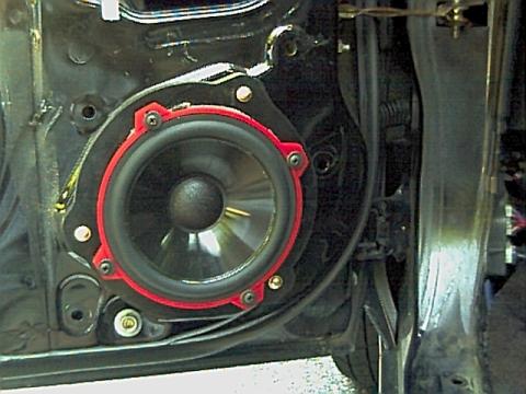
I then connected the speaker to the terminals and screwed the speaker into the spacer ring with the provided screws. Be sure to pre-drill the holes for the speaker screws so you don't split the spacer ring. Lastly, I slid the whole assembly in place and screwed it to the door. Here's the final product:
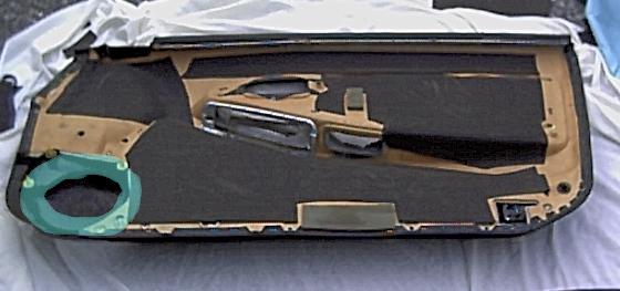
Modifying the door panel
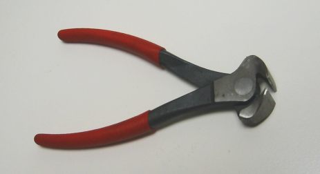
Before you put everything back together, you might need to modify the door panel a little. There's a plastic tunnel/shroud thing on the panel that is designed to direct the sound out through the holes on the bottom front of the door. Unfortunately, since I used a spacer ring, this interfered with the speaker. I just had to trim it back about an inch or so. This can be done with tin snips, diagonal pliers, or easiest of all, end-cutting pliers (also known as nibblers.) A set of end-cutting pliers can be had at any hardware store for just a few bucks and IMHO it's worth buying a pair just for this job. The tunnel/shrowd area that needs to be trimmed back is hi-lighted in the pic below.
The handy tool for cutting the shroud:
Also note that this is a good time to add some sound deadening. This cured a rattle I was hearing, and reduced road noise somewhat. I'm not convinced that Dynamat is any better than the generic stuff you can get from places like PartsExpress.com. I bought a few rolls and put a layer in each door. The door panel is an odd shape, so I had to use several pieces and sort of work it around corners. It's probably better to put the damping material on the door metal itself, rather than the panel, but this approach is much easier and still works reasonably well. With the door panel screwed tightly against the door metal, the damping material will still serve to dampen door vibrations, and it's still a layer of insulation between you and road noise. To each his own.
Before putting the door panel back on, it's a good idea to check the speakers. Play some music at a relatively high volume and make sure there's no rattles or distortion, and that both the woofer and tweeter are working.
Mounting a subwoofer in the cockpit of a MKII
This section details mounting subwoofers in the cockpit. I've seen everything from a single upgraded 5.25" sub in the stock location to twin 12" subs in enormous sealed enclosures, one behind each seat. I went with a single 10" sub behind the passenger seat. As I mentioned above, I think a single 10" or dual 8" subs gives more than enough base for a MKII. Regardless of which route you choose, here are some important things to think about before selecting boxes:
- Most importantly, will you have enough room to slide your seat back and/or recline it enough to be comfortable? What about your passengers? The best sub in the world is pretty pointless if it makes your car uncomfortable to drive / ride in.
- Do you ever use the space behind the seats for storage? If you have T-Tops, where do you put them when you take them out? How often do you use the storage box behind the passenger seat? Will having to move the subwoofer to get to the storage box annoy you in the long run?
- Can you still get to the engine hood release lever behind the driver's door? If you have to move the sub box to get to it, will this also annoy you in the long run?
I chose to use a single 10" box behind the passenger seat. I never use the storage box, so that wasn't an issue. I don't use the T-tops much, but when I take them out they both fit behind the driver's seat. The engine hood latch isn't obstructed, and I still have a flat storage area where I can throw a small cooler or my biking gear. And, of course, the driver's seat doesn't loose any recline. The passenger seat can't be reclined all the way, but I haven't found this to be a big problem.
Options for subwoofer enclosures
There are three options when it comes to obtaining a subwoofer box:
1. Buy a generic, ready-made box.
Dozens of ready-made boxes are available from places like Sound Domain, Crutchfield, and Ikesound. Look for truck-type boxes, which are shallower and fit better. Make sure there's enough mounting depth to fit the subwoofer you've chosen, and carefully measure the area behind the seats. All MKII interiors should be the same, but in reality I doubt that's the case. The shelf area is roughly 7.5 inches deep by 20 inches wide, but measure your own to double check. It's also a good idea to buy the box from a place with a good return policy, just in case it doesn't fit the way you hoped. It's also hard to predict the impact on seat movement without having the box in your car. The place I bought my box from (Crutchfield) was nice enough to let me take it out into the parking lot to test-fit it before purchasing.
2. Buy a custom box specifically made for the MR2
Shawn M. makes custom boxes designed specifically for the MKII MR2, in both 8" and 10" sizes. With the 8" versions, you don't loose any recline room, and the T-tops can still fit behind the seats. Details can be found here: Shawn M. MR2 sub enclosures. Another option is to spec out your own design and take the measurements to a car audio store or cabinet maker. This option may actually be cheaper than building the box yourself IF you don't already own the necessary tools.
3. Build your own
The most time consuming, but also potentially the cheapest and most rewarding, especially if you already have access to the necessary tools. There's lots of great resources for box building out there, so rather than go into detail I'll just say "measure twice, cut once" and then point you to Google. I had already had my fill of working with MDF from the amp rack, woofer spacers, and tweeter mounts, so this option wasn't terribly appealing to me personally. Maybe next time.
I went with the first option, and bought a Q-Logic QLT-.6510sx from Crutchfield. It was reasonably cheap, had enough depth and the proper airspace for my chosen subwoofer (Image Dynamics IDQ-10), and it fit perfectly on the shelf behind the passenger seat (see pictures below). The dimensions of the QLT-.6510sx are 20" wide x 15" high with a 7-1/2" bottom depth and 5" top depth. The airspace is 0.65 ft^3. NOTE: I've been informed that Q-Logic has discontinued the QLT-.6510sx and is now selling a QLT-.6510se ("second edition?"). The se is slightly wider and deeper, at 21-1/8" wide X 13-7/8" high with a 8-1/8" bottom depth and 5-1/4" top depth. I've been told that this newer box does not fit nearly as well. A Google search still turns up some places selling the sx, so perhaps some old stock is still available. Anyway, be sure of what exactly you're getting, and check the return policy in case you're not happy.
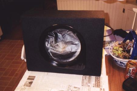
Installing the sub in the enclosure
The QLT-.6510sx came with a medium gray carpet covering that didn't quite match my black interior. I just sprayed the box with some black spray paint to darken it. Before painting I crumpled up some newspaper inside the box to protect the connectors from over spray.
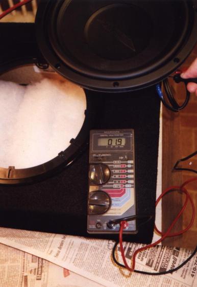
My sub was a dual voice coil sub, with 4 ohm coils. I wired the coils in parallel to achieve a 2 ohm load. Be sure to check the manual for your amplifier, and get a subwoofer with an appropriate resistance. Not all amps can handle a 2 ohm load, especially when bridged. I used a short piece of 12-gauge wire to connect the coils.
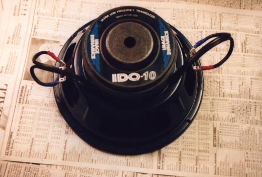
Before mounting the sub in the box, I double checked my coil wiring with a multimeter. The measured resistance varied +/- 0.2 ohms based on how I held the contacts. I was expecting 2 ohms of resistance and deemed 1.9 ohms to be close enough.
I ran a short piece of 12 gauge wiring from the sub terminals to the inside of the box terminals. Then it was just a matter of screwing the ring of the subwoofer into the mounting box. Be sure to pre-drill any holes and use rubber or foam between the sub ring and the surface of the enclosure to prevent any leaks. I also filled my box half full with polyfill. I didn't try it without the polyfill, so I can't comment on what (if any) effect it had. I just followed the recommendation from the sub manufacturer.
Mounting the enclosure and wiring the sub to the amplifier
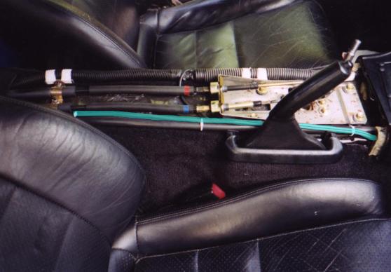
After passing the sub wire through the front firewall and along the passenger side footwell, I ran it underneath the center console, as hi-lighted in the pic below. I would recommend using 12 gauge wire or larger. If you buy generic wire it's not too expensive.
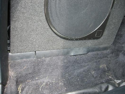
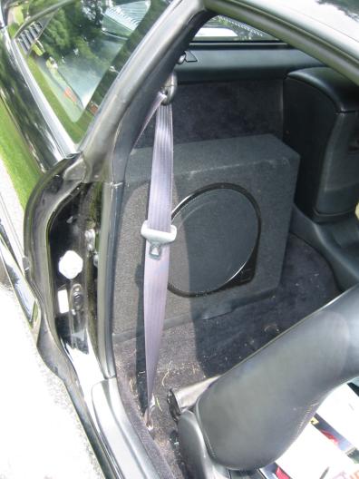
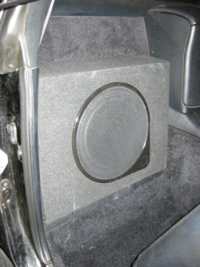
The finished box installed behind the passenger seat
Here are some pictures of the finished sub box behind the passenger seat. The fit is excellent and the box doesn't move around at all. Although the box seems to vary between gray and black in the pics on this page depending on the lighting, rest assured it matches the stock interior very well. It doesn't really matter in the end, though, because once the passenger seat is reclined you can't see the box at all. This is a nice bonus from a "stealth" perspective.
Installing an aftermarket head unit
This section describes the mounting and wiring of an aftermarket head unit. The stock opening is double-DIN size, so just about any head unit will fit. If you decide to go with a single-DIN deck, you can fill the other DIN slot with a storage pocket, a gauge panel, or slide-out cup holders.
Removing the stock head unit
This section describes the removal of the stock head unit. The process has also been covered here, if you want a second opinion. Make sure to eject any CDs before taking the HU out, it's much harder to do so once it's disconnected. Also, if for some reason you plan on reusing or selling the stock HU, turn off the security code before removing it. 90% of the job is removing the plastic trim piece that surrounds the radio, climate controls, vents, and ignition. Once this is out, removing the head unit is trivial.
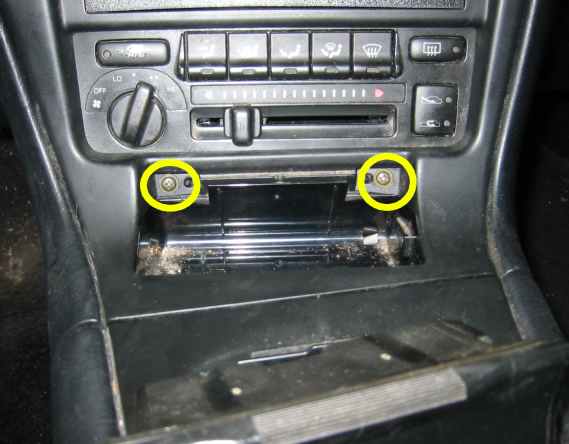
First, pull out the ashtray and remove the two screws shown below.
Then unscrew the shift knob and pull off the shifter boot. It's clipped onto the center console, just pull straight up and it will pop off.
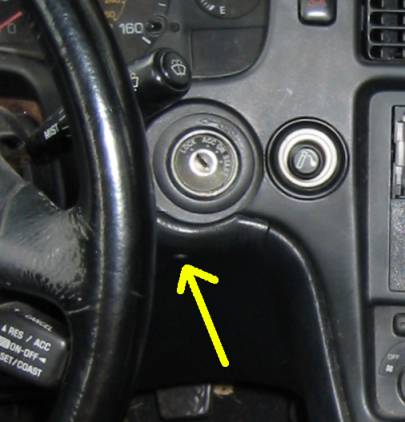
Now remove the screw under the ignition cylinder.
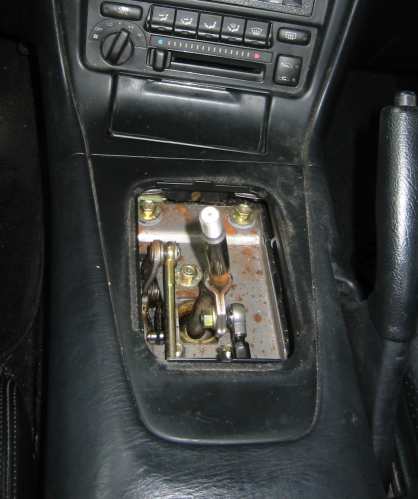
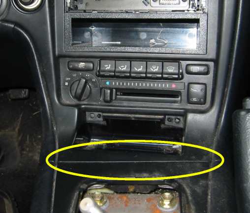
The center console is interconnected with the dash trim piece with two tabs located at the seam circled below. Gently pull up on the console near the shifter until these tabs pop out.
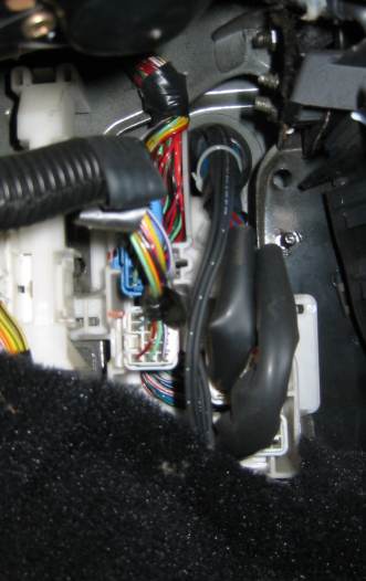
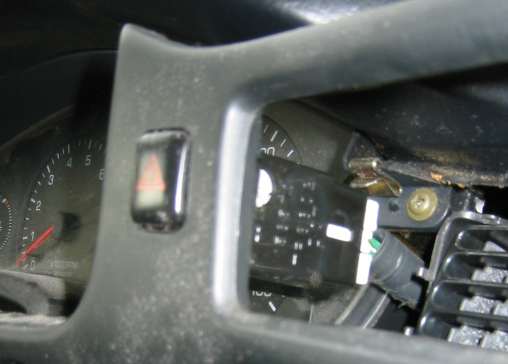
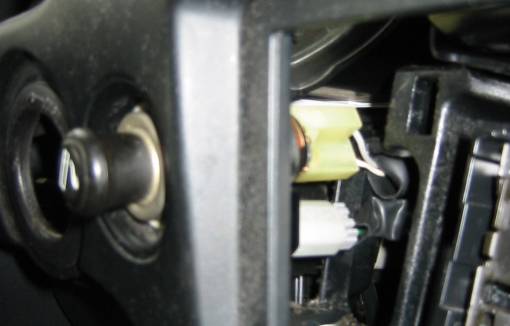
Now for the only tricky part: removing the trim piece. It's held in place by several clips around the perimeter. Just start near the ashtray and work your way around, pulling straight back. The hazard button and cigarette lighter both need to be unplugged to completely remove the trim piece. There isn't much slack in the wires, so pull gently. Once you have enough room, reach through the vent opening and disconnect the hazard button, then reach through the radio opening to disconnect the lighter. Here's pics of the connectors:
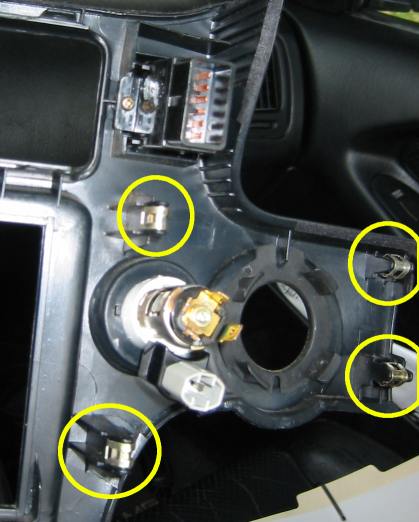
When you get near the ignition cylinder, you'll have to press the trim piece away from the cylinder (think radially outward) as you pull back to get it to clear the cylinder. The picture below shows the back of the trim piece, in the ignition cylinder / hazard / cigarette lighter area. Note where the various clips are.
Set the trim piece aside. The next step is to remove the 4 hex-head screws shown below. They're in pretty tight, so I'd recommend using a 8mm socket with extension rather than a screw driver.
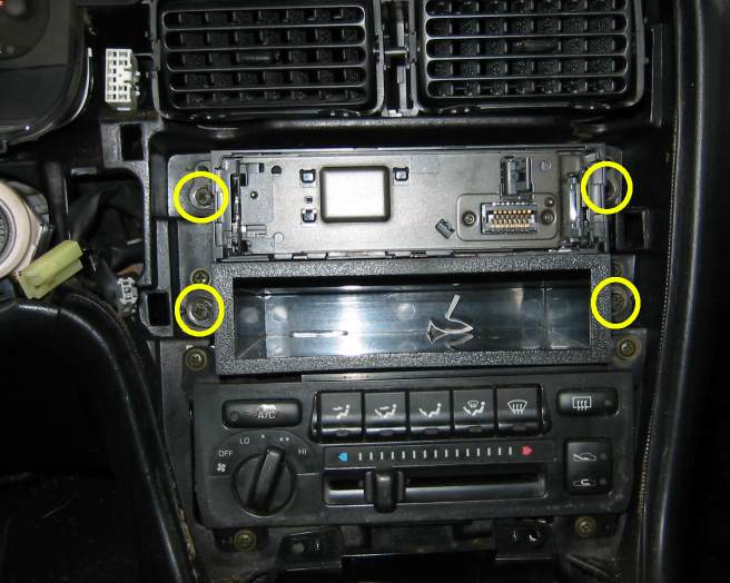
Once the bolts have been removed, the HU should slide straight out. You may have to lift up slightly as you pull backward. Disconnect the harness and antenna and it should come free. Once you've got the HU out, be sure to salvage the two side brackets shown here:
These are standard DIN brackets and should bolt up to any aftermarket stereo.
Salvaging a 14-pin connector from the stock head unit
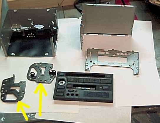
This step is optional, and will result in the destruction of the stock head unit. If your HU has been annoying you lately, this could be a good thing. In the end you'll liberate a difficult-to-find connector for the stock 14 pin harness, which can be handy later. I didn't take many pictures of this process, all you're really doing is disassembling the HU into component atoms. It's built up of interlocking layers of metal cages and circuit boards. Just go slowly, unscrewing every screw you can see. Your target is the bottom circuit board with the 14 pin connector on it. There's a small metal band that holds it in place, the liberated connector and vanquished band are shown here:
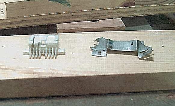
Here's a pic of the connector from the other side. Once you get to the board with the connector on it, you'll notice a series of pins with right angle bends that rise up from the board and go through the back of the connector. Clip these as close to the board as you can, and save as many as you can. Later on, you can solder leads to the back of these pins to access wires in the stock harness. The pic below shows the salvaged connector and some of the pins.
In the end, I'm not 100% convinced this approach is worth the effort. I think you could just as easily poke solid core wire of appropriate gauge into the harness side connector. The salvaged connector approach may be a little more secure, though, since it preserves the locking tab.
Making a wiring harness
The 1991 stock premium system uses a non-standard 14 pin harness. There is now an adaptor for it, but it's somewhat expensive and hard to obtain. It's also the easiest way of integrating an aftermarket head unit. Your options for dealing with the premium wiring are as follows:
1. Splice a more readily available 14 pin plug into the stock wiring
There's a good write-up of this approach here. You can get away with a connector with fewer than 14 pins, since odds are you won't be using all of the stock connections anyway (BEEP and MUTE come to mind). I'd go ahead and use a 14 pin connector, though, just so you have all the connections available in case you or a future owner decides to go back to a stock stereo.
2. Bypass the stock wiring entirely.
If you're running an aftermarket amp, you'll only need 4-5 of the wires in the stock harness anyway, and they can be pulled from elsewhere. This is essentially what I did.
3. Cannibalize the 14 pin female adapter from the stock HU
If your stock premium HU has quit on you, and you don't mind sacrificing it, you can salvage a useable connector from the back as mentioned earlier.
4. Shell out for an adaptor.
After many years with no adaptor available, Autoleads has stepped up and begun offering a plug-n-play solution for the 1991 premium sound system. The part # is PC9-406, and details can be found here
I mostly bypassed the stock wiring, but I did end up pulling switched power from the stock harness using a cannibalized connector. The pinout of the stock adaptor and the wiring codes appear below for reference.
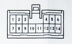
Stock 14 pin connector sources
| Pin # | Signal | BGB wire color | Alternative source |
|---|
| 1 | AMP | pink w/ blue stripe | Not needed (1) |
| 2 | ILL+ | green | Not used (2) |
| 3 | +B | blue w/ orange stripe | Constant power can be pulled from the clock or directly from the battery (use a fuse) |
| 4 | MUTE | black | Not needed |
| 5 | FL+ | white | Not needed |
| 6 | FR+ | red | Not needed |
| 7 | ANT | green w/ black stripe | Not needed (1) |
| 8 | ILL- | white w/ green stripe | Not used (2) |
| 9 | ACC | gray w/ red stripe | Switched power can be pulled from the driver's side kickpanel fuse box, or from the cigarette lighter |
| 10 | GND | brown | The head unit can be grounded to the chassis using any nearby bolt |
| 11 | GND | green | Additional ground, not needed (3) |
| 12 | BEEP | yellow | Not needed |
| 13 | RL+ | brown | Not needed |
| 14 | RR- | blue | Not needed (4) |
NOTES:
(1) The AMP and ANT pins are used to operate the power antenna. If you're keeping the antenna, connect these two leads to a turn-on lead from your head unit. If your head unit has separate amp and antenna turn-on leads, you can connect the antenna lead to the harness AMP & ANT so that the power antenna only raises when listening to the radio, not CDs. Also note that some owners have reported that the ANT lead is black with a red stripe, not green with a black stripe as listed in the BGB
(2) Pins 2 & 8 are listed as unused in the BGB. The information in the table comes from the thread about splicing in an alternate connector linked to above.
(3) This pin is supposedly the signal ground, so this lead is used if you're trying to use an aftermarket HU with the stock amplifiers
(4) Pin #14 is listed as "RR-" in the BGB, but I'm inclined to believe this is a typo and it's really RR+ and therefore consistent with the other speaker wires.
It should also be noted that if you're using the AMP (1) & ANT (7) leads, or the ACC (9) lead, you'll need to retain the stock amplifiers. I'd recommend leaving them in regardless, unless you're on a big weight reduction kick.
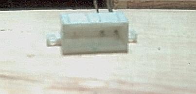
In the end the only pin I used from the stock harness was #9, switched power. I soldered a short piece of wire onto the back of one of the pins salvaged from the stock head unit connector, and then plugged it into the stock harness as shown:
Again, I'm not absolutely convinced this approach is worth the trouble.
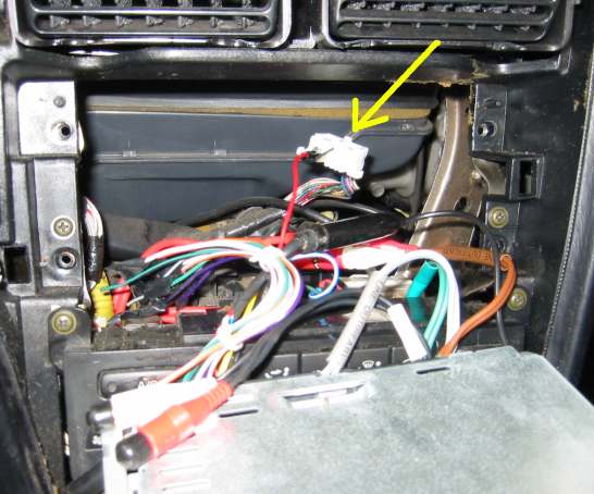
Adapting the antenna
The premium system uses what Toyota calls a "diversity" antenna for radio reception. There are actually TWO antennas, the power antenna mounted next to the spoiler on the passenger's side, and an additional antenna in the windshield. If you ever wondered what the thin wire that runs down the center of the windshield was for, now you know.
The power antenna uses a standard "F" connector and should plug directly into most aftermarket head units. Just connect a turn-on lead to the AMP and ANT leads in the stock harness and you're set. In my case, however, the power antenna had long since quit. I didn't feel like replacing it, but still wanted decent radio reception, so I decided to take advantage of the windshield antenna, which uses a "mini/GM" connector. The antenna plugs are shown below.
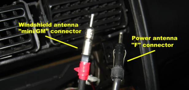
A simple adaptor is used to convert the mini/GM plug to a standard F connector.
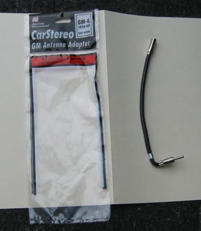
This was American International part # GM-6, similar adaptors are available online from a number of sources.
Power and signal wiring
This section covers power and signal wiring for the head unit. This section will be brief as most of it was covered in the amp wiring section. The constant power and RCAs simply plug into the appropriate connectors on the back of the HU. For the ground, I used a bolt on the passenger's side of the center console.
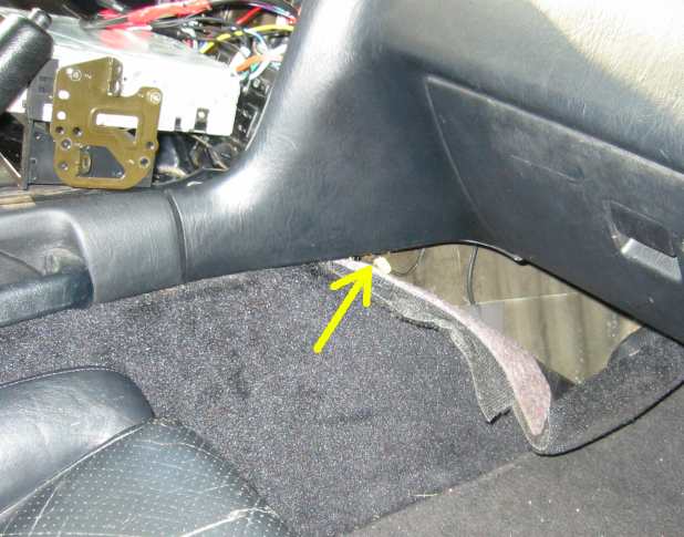
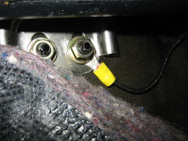
The ground lead is a crimp-on ring terminal on 16 gauge wire, same size as the constant power wire. Here's a close up:
Once everything is wired up, attach the stock brackets to your head unit and slide it back into the dash. Check and make sure everything is working before putting it all back together.
Things I would have done differently
I'm pretty happy with the way everything turned out, but if I had to do it again there's a few things I would have done differently:
- Subwoofer - I would have put a quick disconnect terminal in the wiring near the box itself, and put a handle on the box as well to allow for easy removal during autocross and track days.
- Amplifier - Again, quick disconnects for the speaker & power wiring so I could easily remove the rack as need be. Also, I probably should have just used plywood for the rack. It would have been lighter and cheaper. Plywood doesn't finish as nicely as MDF, but it's under the hood and I never have to look at it anyway.
- Head unit - My next upgrade will probably be a new head unit. There's nothing wrong with the single-DIN MP3 capable unit I have, but a lot of new decks have come on the market since I bought it a few years back. I'd like to take advantage of the stock double DIN opening and fill it with a DVD/Navigation HU with a touch screen interface.
- Tweeters - As I mentioned above, making the mounts was probably more trouble than it's worth. I could have just used plumbers tape, or modified the stock mounts with a bit of bending.
- Woofers - I'm not sure I would have bothered painting the spacers, since they don't really show.
This concludes this how-to guide, I hope it was helpful. Once again, feel free to contact me with comments, corrections, suggestions, or questions at "smspam @ comcast.net". Be sure to put "MR2 audio" or some variation thereof in the subject line, or else it likely won't pass my SPAM filter.
 Up to the top