This page is intended as a how-to guide for replacing the ABS sensors on MKII Toyota MR2s. This guide details the process for replacing the right rear sensor. The left rear appears to be a mirror image, with the advantage that the speed control actuator doesn't have to be removed. I am not sure how applicable this guide is to replacing the front sensors, but hopefully it will be of some use. This page contains:
The ABS system on MKII Toyota MR2s is a 3-channel system that relies on 4 wheel speed sensors. If any of these sensors malfunctions, the ABS light on the dash will remain illuminated and the ABS system will revert to fail safe, power brakes-only mode. While it is not IMHO harmful to the car to drive it in this condition, I would recommend getting the ABS system fixed ASAP due to the added safety benefit it provides. You can determine which ABS sensor is malfunctioning by reading the ABS computer error code, a procedure outlined here:
If the ABS code check reveals a malfunctioning sensor, my recommendation is to replace the sensor. They're available for just under $100 each from places such as partznet.com. If there's an obvious cut wire, you might try to repair it, but bear in mind the wiring is going to undergo lots of vibration and flexing from suspension movement, as well as heat cycling from the brakes. So do a good solder job and insulate it well. Again, my recommendation is just to replace the sensor.
This job is relatively straight forward and doable in an hour or two. The catch I ran into was actually removing the old sensor from the wheel hub. It's a tight fit and tends to rust in place on older cars, and in my case it took an extra hour of struggling to get it free. If you have the time, I would strongly recommend getting to step 7 below first, then soaking the sensor in PB blaster or brake cleaner and letting it sit overnight.
Required tools/supplies:
Disclaimers:
Step 1: Loosen (but don't remove) the lug nuts on the wheel in question.
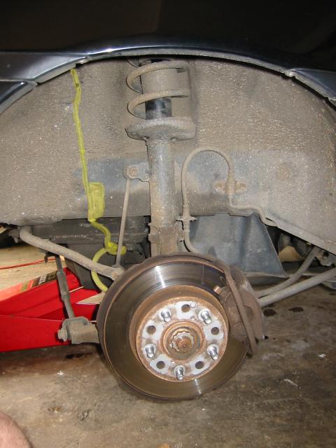
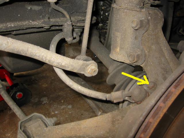
Step 2: Raise the rear of the car enough to remove the wheel. Be sure to chock the front wheels to prevent the car from rolling. Lower the car on to jack stands and remove the wheel. CONFESSION: I did this whole repair with the car supported on the floor jack. Since I was never actually under the car, this didn't seem unsafe to me. Do as I say, not as I do, however, and support the car with jack stands. I've highlighted the sensor in the picture below so you can see where we'll be working.
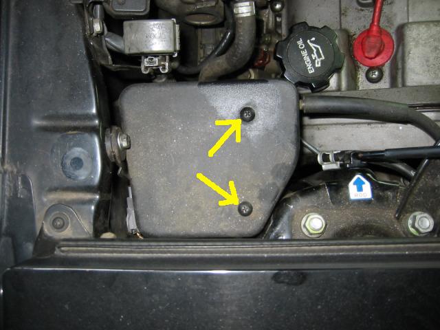
Step 3: We need to get to the ABS sensor plug in the right rear of the engine bay, and to do this we need to move some things out of the way first. Begin by removing the speed control actuator cover. It's held on by two phillips head screws. NOTE: I assume cars without cruise control have no such obstructions, and can skip ahead to step 5
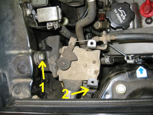
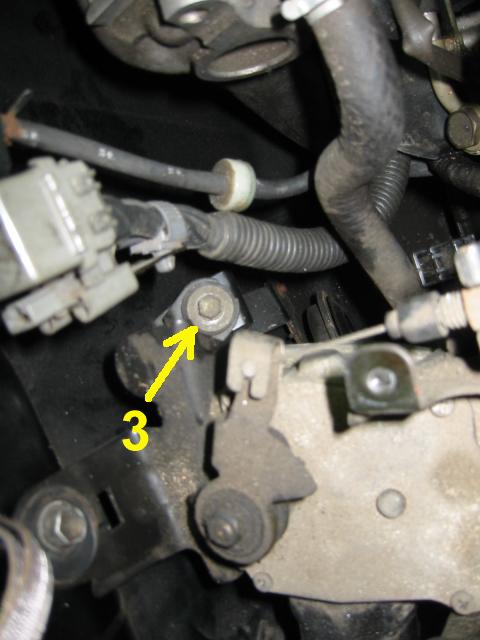
Step 4: Now remover the three 10mm bolts holding the speed control actuator assembly in place. Bolts 2 & 3 are harder to get at, and the wobble tip will be handy here. I actually left 2 & 3 sitting in their slots in the assembly, I just loosened them enough to pull the assembly free. I figured this was easier than trying to reseat them later. Just pull up on the assembly some as you alternate between loosening 2 & 3 and it will eventually come free. When it does, push it towards the oil filler cap to get it out of the way.
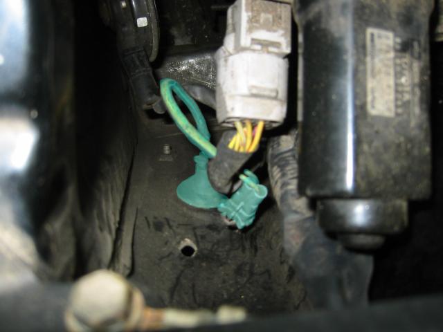
Step 5: With the speed control actuator assembly out of the way, we can now reach down and unplug the ABS sensor. It may be tucked under the thicker part of the wiring harness, but it's there. Just trace it from the grommet in the fender if you have trouble locating it. The clip, wire, and grommet are highlighted aqua-ish in the picture below.
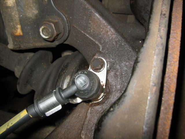
Step 6: Now we move back to the wheel hub and remove the 10mm bolt that holds the sensor. This should be straight forward with a socket + extension. Just watch your knuckles on the various suspension bits.
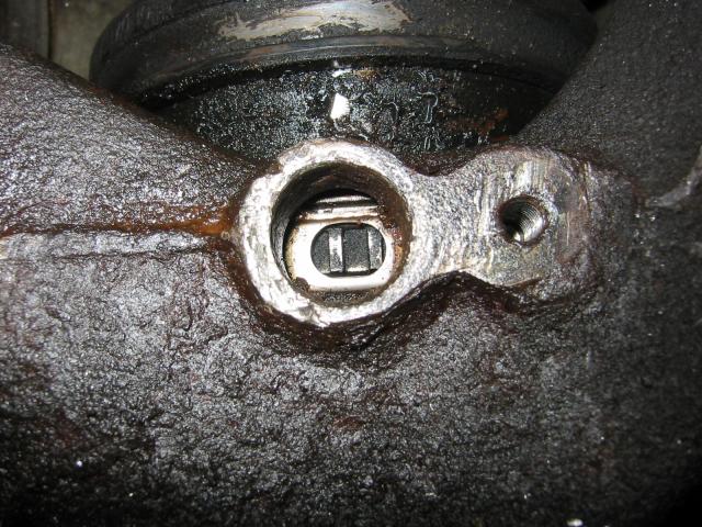
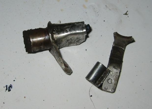
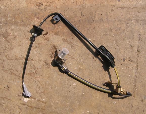
Step 7: Pull the ABS sensor free from the hub. This was the hardest part of the job for me because the sensor was basically rusted in place. The pics below show what it should look like once it's out, and what my now-mangled sensor looked like. Again, this step was an absolute pain for me, and took over an hour of soak-fight-deep breaths-repeat. Eventually I got a pair of vice grips locked on the barrel of the sensor, and was able to rotate it in place. I slipped a large, already mangled flathead between the sensor tab and hub and was able to pry at it slightly. Eventually I was able to pull outwards on the sensor with the vice grips while turning and prying and work it free.
A couple of tips:
Step 7: First, prepare the hole in the hub for the new sensor. A wire brush or Dremel will be handy for removing some of the rust along the walls of the hole. Don't grind out too much, just enough so that the new sensor can squeeze in. I actually used a copper cleaning brush for a 12-gauge shotgun in the chuck of a cordless drill for this step. It's also a good idea to clean out the hole afterwards with some rags or paper towels to remove any other bits of metal or rust. You don't want them messing up the new sensor. The new sensor assembly is shown below.
Step 8:With the hole cleaned out, insert the new sensor and attach it with the 10mm bolt removed in step 6.
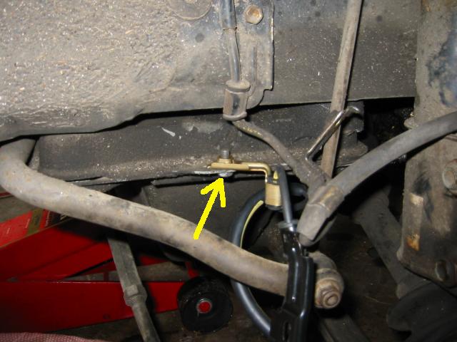
Step 9: Now we need to route the new sensor wire up to the engine bay along the inside of the fender. I found it easiest to remove the old wire from one attachment point, then install the new wire, then move on to the next attachment point. This way you don't lose track of the various bends in the wiring, as you can use the old one for reference as you go. Start with the bolt on the bottom of the fender, and attach the new wire here.
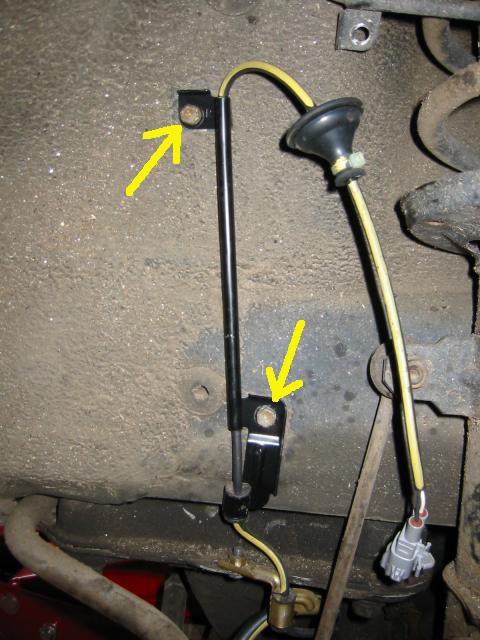
Step 10: Moving up the inside of the fender, remove the two bolts shown, remove the old sensor and attach the new sensor.
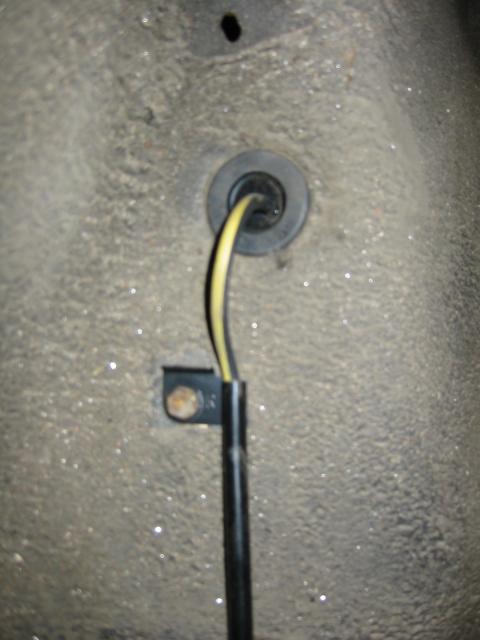
Step 11: Pull the old sensor grommet out. The old sensor should now be completely free and can be set aside. Feed the connector for the new sensor through the hole in the fender and push in the new sensor grommet. It may help to reach down on the engine bay side and pull on the rubber grommet to help seat it.
Step 12: Move the speed control actuator back into place and reattach it with the 3 10mm bolts loosened/removed in step 4
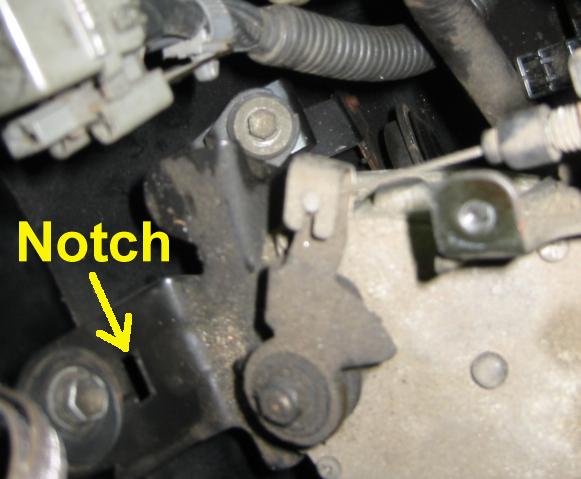
Step 13: Replace the plastic speed control actuator cover and secure it with the 2 phillips head screws removed in step 3. Note that there's a small plastic tab on the side opposite the screws (rear firewall side) that needs to fit into a small notch just below bolt #1 in step 4 above. I shoved the cover piece a few times wondering why the screw holes didn't line up before noticing this.
Step 14: Mount the tire, torque the lug nuts, and lower the car.
That's it, clean up the tools and you're all finished. Note that in order to get the ABS working again, though, you'll need to reset the code, a process described here:
 Up to the top