The Effects of Rotational Inertia on Automotive Acceleration
This page contains an examination of the effects of rotational inertia on automotive performance, specifically acceleration. For each component (wheels, brakes, etc.) there's a short description of the effects and a JavaScript calculator.
This is largely an academic treatment of the subject. The math and physics are correct, but simplified from the real world case. See the lengthy disclaimers at the bottom. Nevertheless, it should be usefull for estimating the relative impact of a component change.
I'm not perfect. Far from it. My master's thesis concerned the dynamcis and control of rotating machinery, and I've been working as a mechanical engineer for the past decade, so I'm pretty well grounded in this stuff. On the other hand, this page was written on my own time and generally late at night, so I'm bound to have bungled a thing or two. Use it at your own risk.
Comments, corrections, and suggestions are welcome and should be sent to "smspam @ comcast . net" with "rotational inertia" in the subject line.
Shaving a pound from your tires is equivalent to shaving at most 2 pounds of non-rotating weight. That's PER TIRE, so a pound off each tire could worth close to 8 pounds of weight reduction. For wheels, the multiplier is closer to 1.6, so saving 5 pounds per wheel (20 total) would feel like a static weight reduction of 32 pounds. For brake discs, it can be as low as 1.2. Regardless of the equivalent weight ratio, you're best off reducing weight as much as possible, as you might expect. For flywheels...you'll have to read the detailed section. Sorry.
Two quick calculators here, to help get the feel of things. The first gives you the rotational inertia for a disc of arbitrary mass and radius. Set the inner radius equal to the outer radius to simulate a thin band.
This second calculator gives the rotational inertia for a cylinder-shaped component of known material construction and dimensions, but unknown weight.
NOTE: The density for carbon fiber given above is a very rough estimate. Actual density will vary with the matrix used, the lay up, and a number of other factors.
This section introduces the concept of equivalent mass. This is what allows us to make such statements as "a pound on a tire is like two on the frame".
First, let's assume a given rotating component has a rotational velocity which is directly proportional to the vehicle's speed . Neglecting tire growth and slip, this is essentially true of every component downstream of the transmission. For flywheels and such, we'll do the calculation in each gear. Let's define a ratio such that:
[1]
that is, the ratio between the components' rotational velocity and the vehicle's linear velocity. The vehicles' speed is equal to the rotational velocity of the tire, , times the rolling radius of the tire , or
[2]
Next let's define a gear ratio that relates the rotational velocity of the component in question to that of the tire by
[3]
So a drive shaft that turns three times as fast as the drive wheel would have a gear ration of 3. Substituting equations [2] & [3] into [1] gives us
[4]
So now we can determine the ratio from known quantities (the dynamic radius of the tire and the component's gear ratio). Let's see what good it does us. The total energy stored in the object in question is a combination of its translational kinetic energy and its rotational kinetic energy, or
[5]
Substituting equation [1] into [5] gives us
[6]
We want to express this total energy as the non-rotating energy of some equivalent mass . So let's set the left side of equation [6] to the kinetic energy of this equivalent mass at the same speed
[7]
Simplifying gives us
[8]
In other words, we can describe the equivalent non-rotating mass of any rotating component as a function of its true static mass , its rotational inertia , and the ratio defined above. Note also that this relationship is independent of the vehicle speed , so the comparison is valid at any velocity, and is independent of vehicle power.
Just to re-state: The total translational and rotational inertia effects of a given rotating component can be expressed as an equivalent non-rotating mass. So when we say "a pound on the tires is worth two on the frame," we're saying the equivalent mass of a tire is twice its static mass. The calculators below will display both the equivalent mass of the object, and the equivalent mass ratio. The higher the ratio, the more valuable weight reduction from a given rotating component is.
Lastly, one caveat: Here I've defined equivalent mass as the sum of the static mass + effective mass due to rotational inertia effects. It's more common to use "equivalent mass" to refer to JUST the rotational component. I use this notation so that the equivalent mass to static mass ratio is always > 1.
The high school physics answer is that the rotational inertia effects braking exactly as much as it effects acceleration. After all, anything you spun up must now be spun down. As usual, though, the high school physics answer is wrong in the practical sense. First off, you don't need to de-spin everything. You can put the clutch in and come to a complete stop with the engine and flywheel still happily revving away. More important, though, is that acceleration is power limited, and braking is traction limited (for the most part, anyway). Let's look at this in more detail.
When you accelerate, the engine has to spin up the various rotating bits of the drive train and use the remaining power and available traction to accelerate the car down the road. As long as you're not traction limited, any reduction in rotational inertia amounts to more engine power that's available for accelerating the car. If you ARE traction limited, say in first gear, then rotational inertia reductions won't improve your acceleration in THAT PHASE of acceleration...though it will likely help on the high end when you're no longer traction limited. And the static weight reduction that usually accompanies rotational inertia reduction will still be of benefit.
When you slam on the brakes, the brake pads have to de-spin wheels and drive train, and the tires' contact patches have to slow the car. This means that if your brakes can already lock up all four tires (and any healthy brake system should be able to, ABS notwithstanding), reductions in rotational inertia won't help. You can already bring the rotating assemblies to a complete stop at speed, it's the tires traction with the road that limits your stopping distance. This is for a single panic stop; rotational inertia reductions will still pay benefits (albeit small ones) in terms of reduced brake load (heating) and better fade resistance for repeated stops.
In both cases, rotational inertia has an impact when you're power limited (in terms of engine power or braking power), but becomes non-important when you're traction limited. The reason why rotational inertia is more important for acceleration is that the average street car is power limited under acceleration and traction limited under braking. And just to be clear, lighter wheels an tires and such will STILL HELP, it's just that you won't get the multiplicative effects given by the calculators below.
The effects of rotational inertia on handling are beyond the scope of any little JavaScript calculator I could devise, and hence are beyond the scope of this page. In short, it's generally best to reduce unsprung weight as best you can. It's also often worth it to take the hit in rotational inertia for bigger wheels and tires, if it means a larger contact patch.
This section contains the JavaScript calculators for the various components. We'll start with the tires and work our way back through the drive train to the engine. A few notes:
These calculators give you the equivalent mass of a given rotating component. Nothing more. There are obvious cost, structural, and safety concerns that apply to a change in equipment that aren't captured here.
Note also that most of the sections have a tire rolling radius input, since the equivalent mass ratio of drive train components depends upon the ratio of rotational speed to road speed, as shown in equations 2-4 above. For convenience, the tire size you enter in the first section is carried through to the others by default.
You can enter weights and dimensions in english or SI units, but all the internal calculations are done in SI, and the results are displayed in SI as well. Google has lots of handy converters if you want to see the various results in english units. I'll add english outputs when the 20th person asks for them.
I've checked these calculators for basic accuracy, but GIGO still applies. Enter a negative mass or zero radius and there's no guarantee what will happen. There's also a chance I've bungled something, so if you find what seems to be a bug, let me know (after checking the FAQ, of course.)
The inertia of the tire is modeled in two parts, as shown below. The sidewalls are treated as discs with an inner diameter equal to the wheel diameter, and an outer diameter equal to the static diameter of the tire. The tread face is treated as a band with a diameter equal to the static radius of the tire. There are some simplifications here; an actual tire has a thicker portion at the base of the sidewall to form a bead, for instance.
I'm assuming you know the weight of the tire, but NOT of the component parts. If you actually sliced a tire apart to weigh the sidewall and tread face individually, then I salute your dedication to science. Anyway, the tread to sidewall thickness ratio in the calculator below allows you to specify the relative thickness of the tread face compared to that of the sidewall. Think of it as an area-specific relative mass ratio. Some number around "2" is probably reasonable, but it doesn't make a huge difference in the final equivalent mass, especially for low profile tires.
Wheels
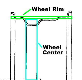
The wheels are modeled in two parts, as shown below. The rim itself is treated as a band of constant diameter equal to the rim diameter. I figure the effects of raised lips and drop base rims cancel out, more or less. The center section is modeled as a series of slender rods (think spokes) of length equal to the rim diamter. I think this is more accurate than modeling it as a solid disc, since rims tend to have more open area around the perimeter and are essentially solid at the hub face. There's an entry for rim mass as a percentage of total wheel mass. This will vary with wheel construction type and the width of the wheel, but it's not uncommon for half or more of the total wheel mass to be contained in the rim. If you've disassembled your three piece wheels and weighed the parts individually, let me know what you came up with.
Note that in addition to the rotational inertia effects, changing the size of wheels and tires effects the gear ratio as well. These changes in gearing are modeled in the numerous drag calculators out there and aren't included here. Also note that these equivalent masses are for ONE tire or wheel...multiply by 2 or 4 as appropriate to see the full effect on performance.
The effect of lugnuts is basically negligible. They're fairly light to begin with and close to the center of the hub. The calculator is included here for completeness.
In terms of total performance, you aren't likely to "upgrade" to smaller discs or drums. Well, maybe on a dedicated drag car. For a road car, though, the more likely path is larger hardware for improved braking and fade resistance, with the increased rotational inertia just being a necessary evil. If you're stuck using drums, for instance, you most likely would happily take the inertia hit on finned drums if it keeps your brakes from cooking. That having been said, there's still inertia reductions to be had if your looking at, say, a two piece rotor with a lightweight hat, vs. a solid. This calculator is also useful for seeing if the $5000 carbon disc option on your next super-exotic is really worth it or not.
My apologies in advance for the dinky, cast iron, un-vented, 4x100 discs & drums in the pics below. It's what I had on hand at the time.
Brake Discs
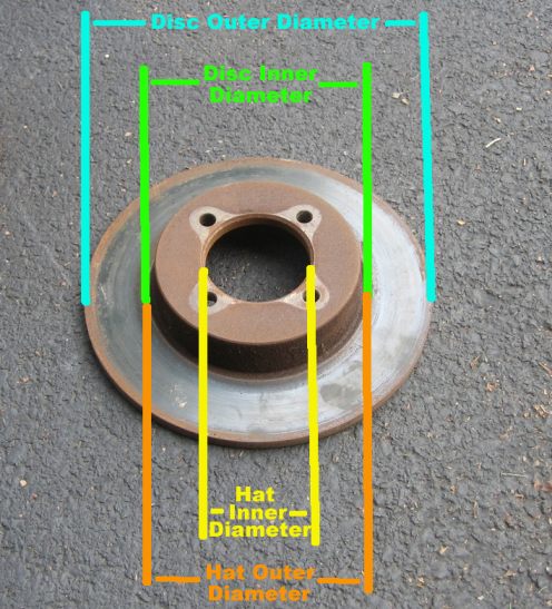
Disc brakes are modeled in two pieces; the friction surface or disc itself, and the hat or hub portion. As the pic below shows, the inner diameter of the disc is usually equal to the outer diameter of the hat.
Brake Drums
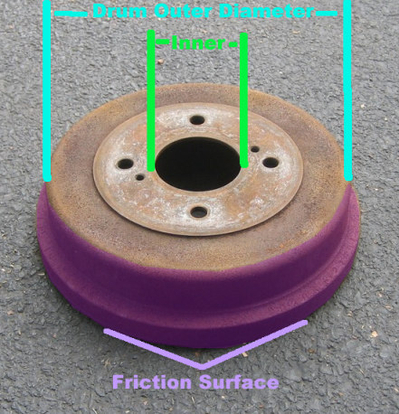
Brake drums are modeled much like wheels...a band for the friction surface (as with the wheel rim) and a center section/hub. The key difference is that with brake drums, the center section is modeled as a solid disc rather than a collection of spokes. As with the wheel calculator, there's an input to specify the mass of the friction surface as a percentage of total drum mass. 50% strikes me as reasonable. The portion of the drum counted as "friction surface" is hilighted in purple in the pic below.
This section covers drive shafts, and axles/half shafts. The principle difference being that axles and half shafts benefit from the final drive ratio and turn even slower than the driveshaft, so the effect of rotational inertia is further reduced. For drive shafts, "gear ratio" below should be the rear-end ratio. For axles and half shafts, gear ratio should be 1 (unless, that is, you have an H1 or other vehicle with gear reduction hubs...in which case you're probably not too worried about acceleration anyway.)
Note: For front engine cars with a rear transaxle (97+ Corvettes, Porsche 944s, etc), the situation becomes more complicated, as the driveshaft must be accelerated once in each gear, as with the flywheel below. I'd recommend computing the driveshaft inertia from the calculators above and plugging it in as a clutch / flywheel to see the effects.
This section is the most complicated and hence the most long winded. My apologies in advance.
First off, a change in flywheel may effect revability, ease of speed matching shifts, ease of pulling away from a stop, NVH, etc...none of which will be discussed here. So, that having been said, how does a lightweight flywheel help in terms of acceleration? In short, a lot...or not at all. Bear with me for a second.
We're staged at the tree, in first gear, engine near redline, clutch pedal on the floor ready to be side-stepped, warranty ready to be voided. Light goes green, we side step, RPM drops, car surges forward, RPMs climb again, clutch starts smelling expensive. What has happened in that short time is that we've converted the rotational energy stored in the flywheel to forward motion. Now we're trying to spin it up again. To a lesser extent, this happens at EVERY gear change. The energy stored in the flywheel goes towards spinning up the rest of the drive train and moving the car forward, and then the engine works to spin the flywheel back up to near red-line speeds. So is it better to reduce or increase the inertia of the flywheel? Before we answer that, a few points:
Not all flywheel energy is converted to forward motion. Some is lost to clutch slip, in the form of heating and ablation of the clutch disk. How much is lost? Depends on the speed difference of the clutch face and flywheel, the condition of the flywheel surface, the grippiness of the clutch, the speed of the shift, and some other factors I'm probably forgetting. Some of the energy is also lost to engine friction, in the form of RPM drop between shifts. So there's no definite answer to this question. As such, I've left it open in the calculator below. "Recovery Percentage" is the percent of flywheel rotational energy that gets converted to forward motion after each shift. Take your best guess. Also note that even if 100% of the flywheel energy is transferred to the drive train when you shift up, you're still likely to lose some of that energy to instantaneous wheel spin (aka "chirp").
A heavy flywheel can load the engine. This is not necessarily a bad thing. If your car is turbocharged, you can load it against the flywheel to help spool the turbos before launching...assuming your timing is good enough. And for a car with a narrow power band, the flywheel can help keep the engine in the sweet spot between shifts.
The flywheel energy stored in first gear is "free". "Free" at the drag strip, anyway. Meaning time and energy spent spinning up the flywheel when staging doesn't count against your E.T. In fact, in the extreme case, a huge flywheel could actually make your car quite a bit faster. For instance, take a 3000lb car with a 100hp engine and an enormous flywheel. You could theoretically run a 10 second quarter mile...if you were allowed a few minutes to spin up the flywheel in the staging lane, and could find a way to dump the stored power without breaking anything. Like I said, this is an extreme example just to make a point. Flywheel energy storage systems can have tremendous power to weight ratios, but are a challenge for mobile applications due to gyroscopic forces and safety concerns.
All that having been said, the calculator below will show you that the equivalent mass of the flywheel is HUGE, especially in lower gears. It's not uncommon for the equivalent mass of a flywheel to be 10x its static mass. Mitigating this somewhat is the fact that the equivalent mass is most significant in 1st and 2nd gears, and you may be traction limited there anyway.
This calculator will display the results in two forms. The first is a raw equivalent mass calculation for each gear. This gives the equivalent mass assuming you accelerate from 0 RPM to redline in only one gear. Not terribly realistic, but it shows the diminishing effects of flywheel rotational inertia in higher gears.
The second presentation is "constant equivalent mass", for lack of a better phrase, and is a bit more meaningful. This accounts for launch RPM (free flywheel energy) and the recovery of energy between shifts, at whatever percentage you specify. The equations are a bit involved, so I'll explain by example instead. Bear with me on this one...
Let's say you have a 20 gallon water tank in your car. Accelerating it from idle to redline in first gear (say 30 mph) takes a certain amount of work. As you shift in to second you trigger a quick dump valve, leaving you with 12 gallons of water in the tank. In second gear you accelerate this mass of water from 30 to 60 mph. Now you shift into third, and dump 7 more gallons. You accelerate the remaining 5 gallons of water from 60 to 90 mph, and we'll stop there for now. Accelerating this variable mass of water from 0-90 mph took a certain amount of energy. The constant equivalent mass is the CONSTANT amount of mass that takes the same amount of energy to accelerate from 0-90 mph. Note that it's more than a simple average, since it takes into account the relative gear ratios, the energy recovery, and launch RPM.
Note that this calculator is appropriate for clutch discs, transmission input shafts, and any other component whose speed varies directly with engine speed. It works for accessory pulleys, too, if you account for the pulley ratio.
This may seem like an awful lot of trouble to go to, and it is. You might be wondering if there's a simpler way to account for rotational inertia effects on performance, and there is. Experience has shown the total equivalent mass of the typical car can be estimated with following engineering rule of thumb:
This gives equivalent mass of the entire car, rotating bits and non rotating bits alike, as a function of its static mass and total gear ratio . Total gear ratio is just final drive ratio * current transmission ratio. The 0.04 term above accounts for the effects of the wheels, and the 0.0025G2 accounts for the rest of the drive train. This equation works because the mass of things like wheels and drive shafts tends to scale with the mass of the car. The equation was taken from the course notes of T.C. Scott's Automotive Engineering circa 1994.
A quick example: Take a 3,000 pound car with a final drive ratio of 3.33:1 and a first gear ratio of 3:1 (chosen so that = 10). Plugging in gives us:
or
which gives us
So as you see, rotational inertia effects can add ~30% or more to the effective mass of a car in lower gears. In higher gears, it can be as little as 5%. Here's one last calculator that implements the above equation:
You didn't account for tire growth with speed
True. I didn't account for the reduction in static radius due to loading, either. I think it's a wash at this level of detail. I suspect the effect is in the <5% range.
Pounds are not a unit of mass.
True. Promise me you measured the weight in pounds of the component in question somewhere near the surface of the earth, and I'll promise that you won't have to see a slug.
The geometry of component X is over-simplified.
Probably true. The tools are here, though, to calculate the rotational inertia of any complicated combination of bits you care to build up. At some point you're better off building it in Pro-E, and letting IT tell you that the simple model was within 10% :) Another approach is to determine the rotational inertia of the part experimentally using the pendulum method, as described here
I made my tires lower profile, for the SAME rim width, and rotational inertia increased!
Look closely...RI decreased, but the EQUIVALENT MASS increased. The smaller tires have to be spun faster to reach the same linear speed, and the shorter sidewall effectively moves the mass closer to the rolling radius.
I changed the units for density in the simple cylinder calculator, and it didn't change the density number, so it's not correct for material X
The material dropdown box uses the onChange method to populate the density field, so you'll have to reselect the material to get the correct density in the new units. More specifically, you'll have to select a different material, then re-select the one you want. Bit of a pain, I know. If there's a more direct way to do this, I'd be happy to hear about it. One thing I didn't want to do is have it change what's in the density box whenever you change the units...since I suspect people will type in the values first and select the units next.
I've got an AWD car, which tire size should I use, front or rear?
Use the wheel for which the stated gear ratio is valid. If you're computing the equivalent mass of a rear half shaft, use the rear tire size. If you're computing the equivalent mass of the intermediate shaft between the center differential and front differential, use the front tire size (and the front diff's gear ratio).
What about the horsepower increase from a lighter flywheel? I've seen gains on a dyno.
A flywheel won't increase horsepower. The typical wheel dyno doesn't measure horsepower...it measures the rate at which the car's engine can accelerate a rotating drum of known inertia. The engine has to accelerate the drive train components as well, so a reduction in drive train rotational inertia will show up on a dyno run as a perceived horsepower increase.
 which is directly proportional to the vehicle's speed
  . Neglecting tire growth and slip, this is essentially true of every component downstream of the transmission. For flywheels and such, we'll do the calculation in each gear. Let's define a ratio
  such that:
 [1]
[1] , times the rolling radius of the tire
  , or
, or
 [2]
[2] that relates the rotational velocity of the component in question to that of the tire by
 [3]
[3] [4]
[4]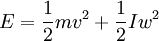 [5]
[5]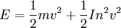 [6]
[6] . So let's set the left side of equation [6] to the kinetic energy of this equivalent mass at the same speed
 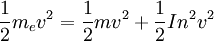 [7]
[7]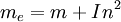 [8]
[8] , its rotational inertia
  , and the ratio
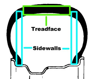

 . Total gear ratio is just final drive ratio * current transmission ratio. The 0.04 term above accounts for the effects of the wheels, and the 0.0025G2 accounts for the rest of the drive train. This equation works because the mass of things like wheels and drive shafts tends to scale with the mass of the car. The equation was taken from the course notes of T.C. Scott's Automotive Engineering circa 1994.


 Up to the top